1. Goal
Learn the line detection function of the AI vision sensor and implement automatic line following with CoCube.
2. Materials
Line following map, downloadable and printable on A3 paper.
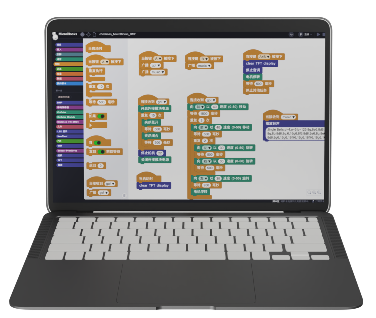
3. Software Platform
4. Algorithm Knowledge
Reference Tutorial
Documentation: Algorithm Introduction — Line Detection
Block Descriptions
- Sengo 1 Initialization Block
The initialization block must be executed before using the camera. It is usually placed under the "when started" hat block.

- Sengo 1 Set Mode Block

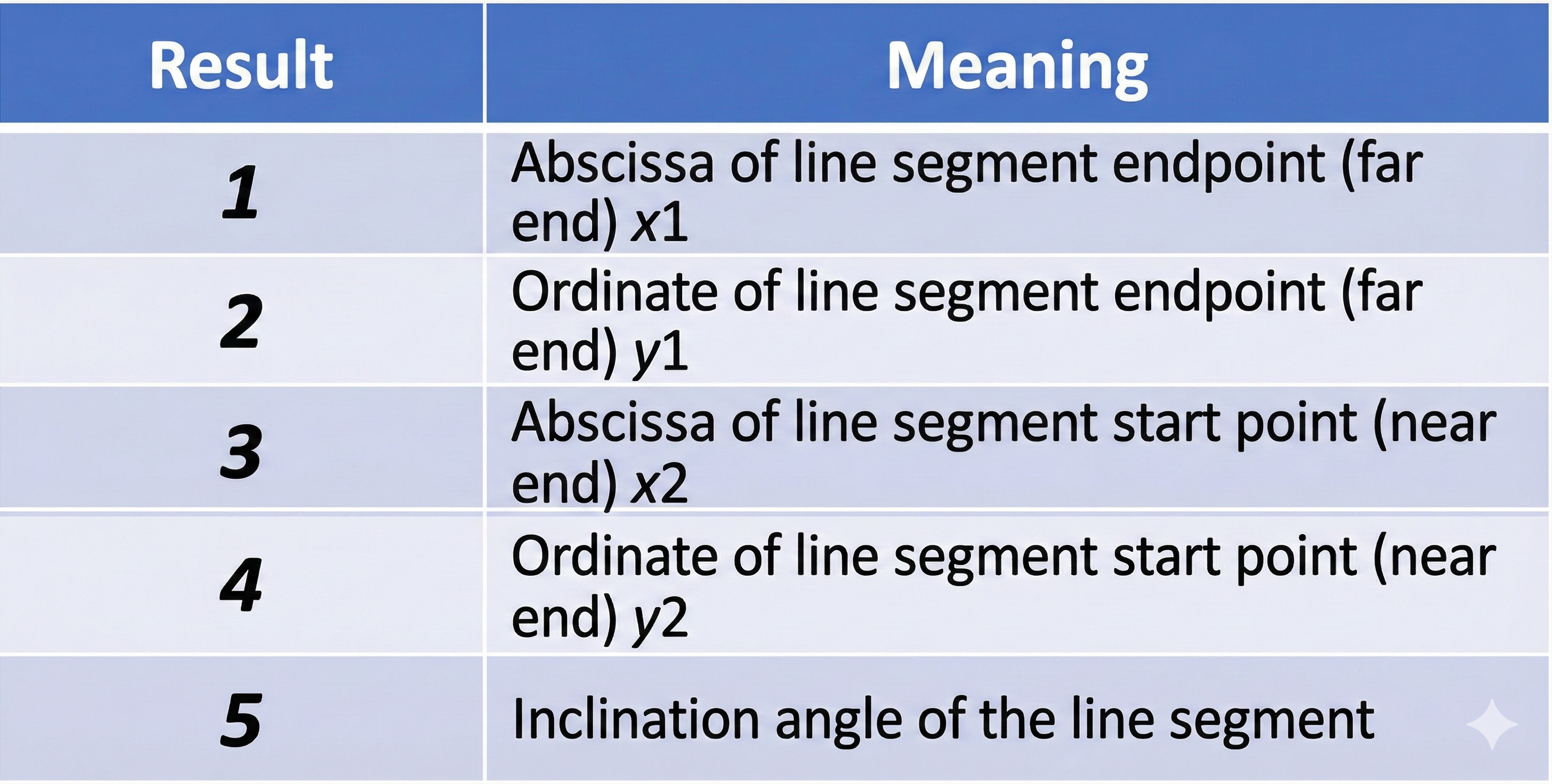
- Sengo 1 Line Detection Attributes

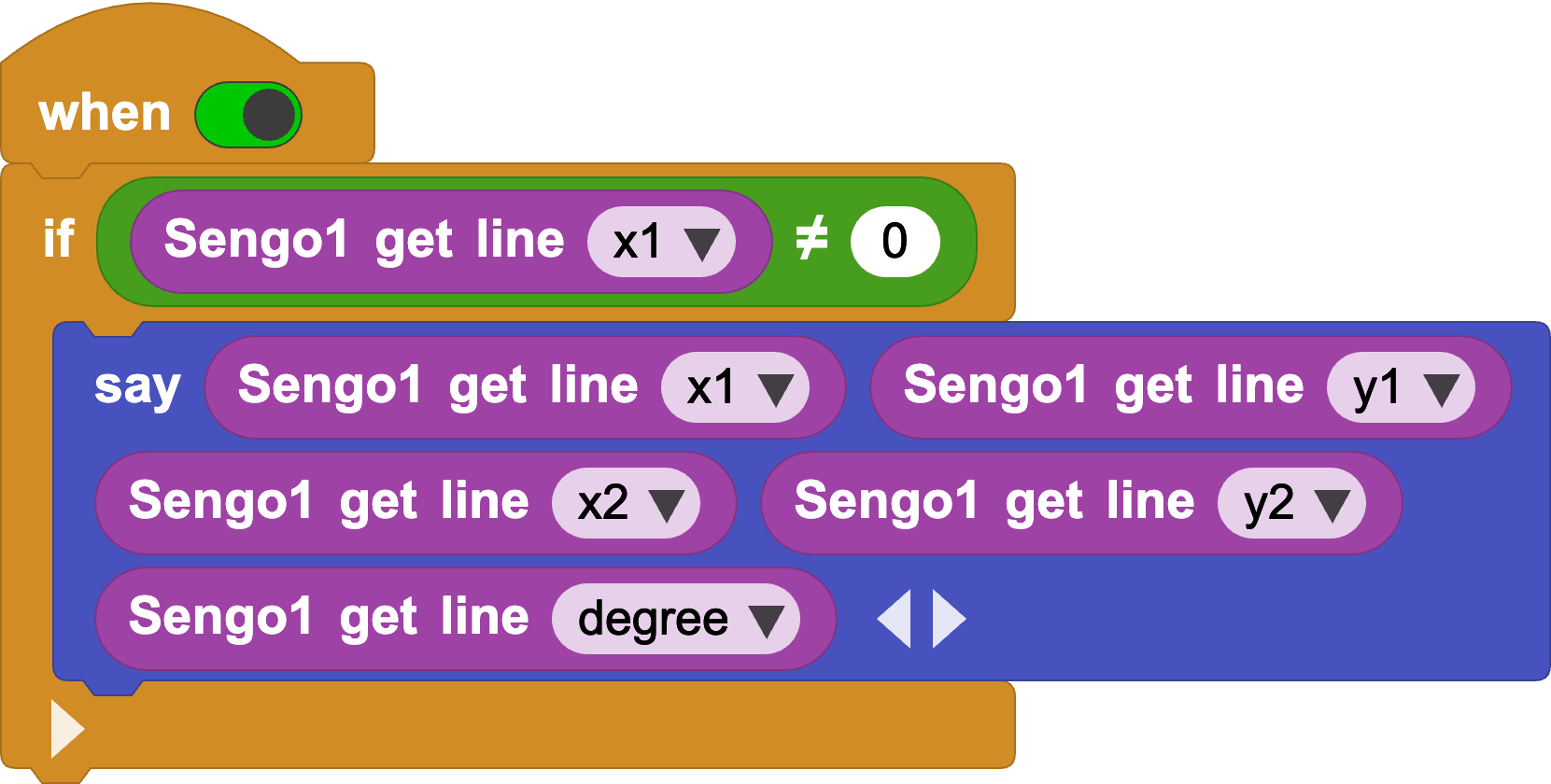
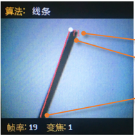
Returns the attributes of the detected line, including the end point x1 (top), end point y1 (top), start point x2 (bottom), start point y2 (bottom), and the tilt angle of the line segment.
Tips
The background and lines should be clearly distinct (e.g., black lines on a white background). If the background is cluttered, lines in the background might be detected.
The line thickness should be moderate—neither too thin nor too wide.
Generally, during line following, the first line segment detected is the one at the bottom of the screen, followed by branch segments.
5. Programming
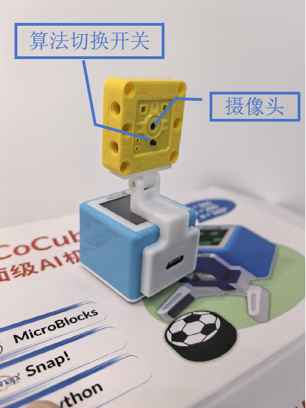
Connect Device: Connect the MicroBlocks IDE to the CoCube robot via wired or wireless connection, and attach the AI vision sensor to the front of the CoCube robot.
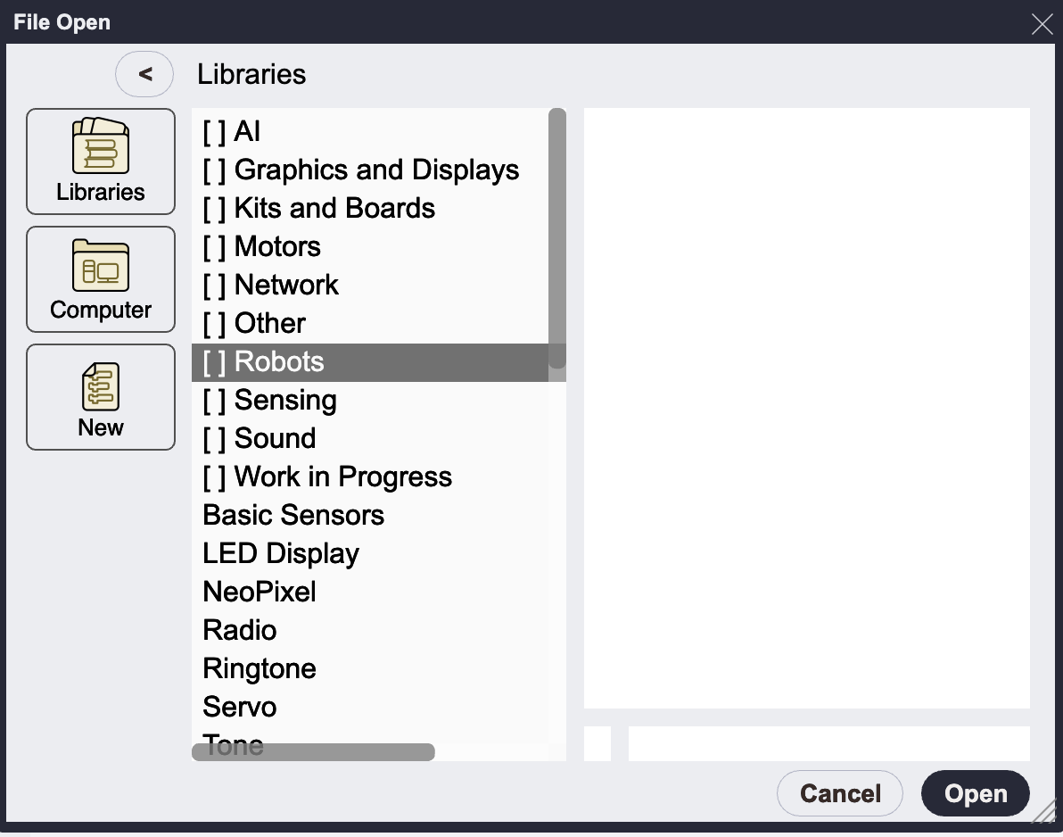
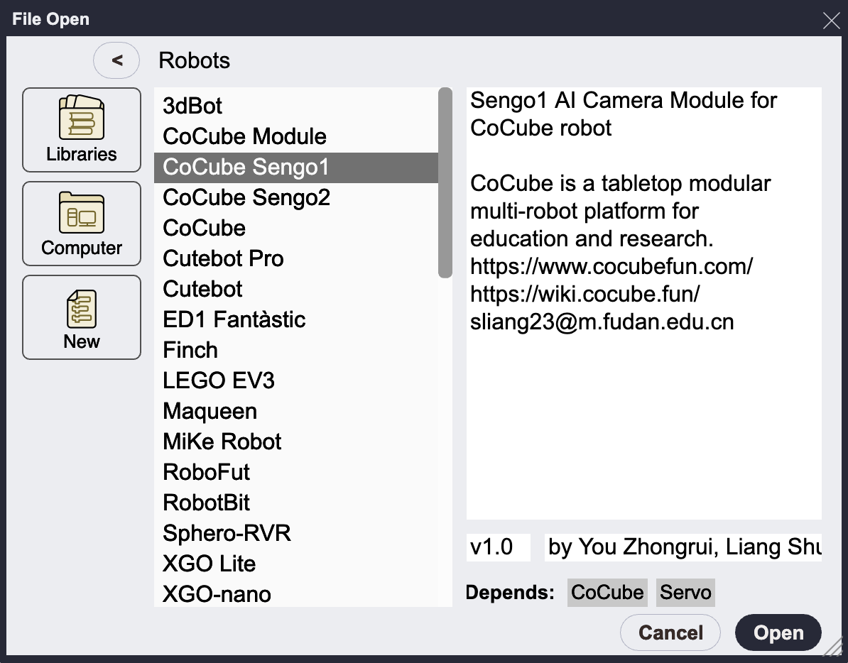
Load Libraries: Add "CoCube Sengo1" or "CoCube Sengo2" from the robot library. The choice depends on your camera hardware model; there is no significant difference in usage, though Sengo2 offers better performance. This tutorial uses the Sengo1 library.
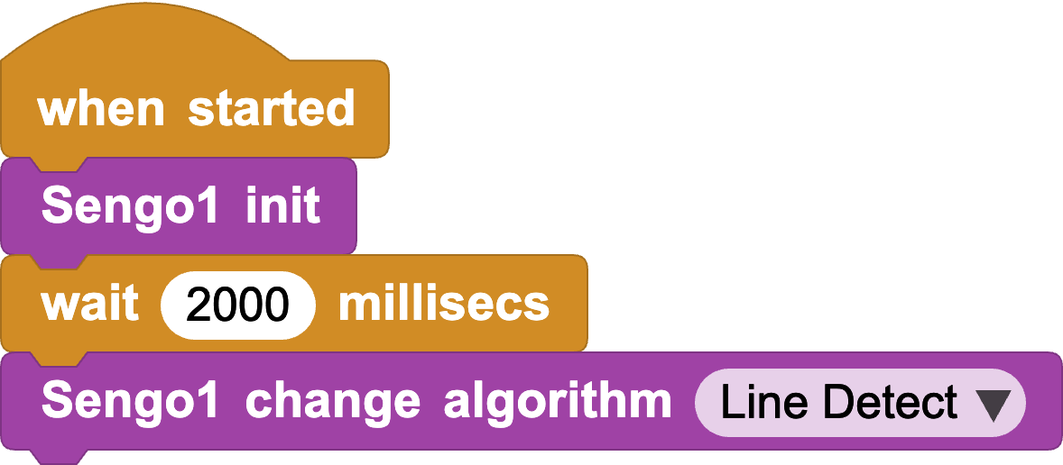
- Camera Initialization: Initialize Sengo1 at startup and set the camera's algorithm mode to Line Detect.
- Line Detection: Determine if a line is detected. If so, output its 5 attributes. You can observe the line's position and angle in real-time.
Now consider how to keep CoCube on the line based on its position and angle. Since CoCube uses tracked differential drive, it needs to adjust the speed of the two wheels to correct its steering when it deviates. This is a form of negative feedback control. We need to determine when to adjust the steering as shown below:
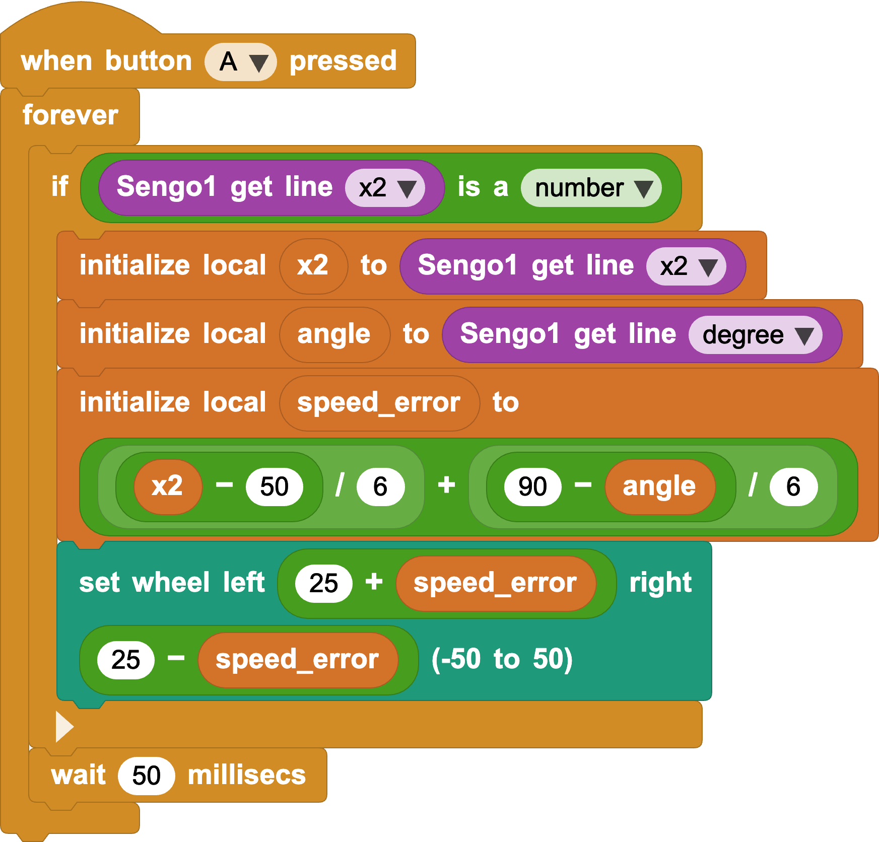
1. When the line position is to the left, it means CoCube has deviated to the right. To return to the center, we calculate the difference between bottomX and the screen center (50), then divide by a proportional coefficient to get a speed difference value, defined as error1.
2. When the line angle is not 90 degrees (indicating a turn ahead), we need to steer to follow the line. We calculate the difference between 90 degrees and the angle, then divide by another proportional coefficient to get a speed difference value, defined as error_2.
The final left wheel speed equals base speed (default 25) + error1 + error2, and the right wheel speed equals base speed (default 25) - error1 - error2.
(Note: error1 and error2 use negative feedback to adjust wheel speed based on actual error, thereby reducing the error.)
- Write Your Own Program: With the debugging code above, try using other parameters as negative feedback terms for higher precision, or combine more functions!
Reference Code: Sengo1 Automatic Line Following
Reference Code: Sengo2 Automatic Line Following